EXECUTIVE SUMMARY
Advances in manufacturing have enabled composites to be made with more complex geometries. This can be used to produce parts with improved structural properties and performance, but that are more challenging to inspect. Such geometries include curved parts, which can be more difficult for ultrasonic transducers to conform to and thus properly inspect.
Often specialist solutions are needed. However, we can successfully inspect curved parts, including small radii, using our transducers with our standard delay line made of Aqualene. This slightly rubbery material helps with conformance to rough and curved surfaces, ensuring the ultrasound is transmitted into the part. The ability to inspect curved surfaces is demonstrated in the following capability study, where reflectors embedded in a tight corner radius of 0.09″ thick carbon fiber laminate were clearly detected and sized using the dolphicam2 platform.
![]()
INTRODUCTION
Advances in manufacturing have enabled the production of composite parts with more complex geometries. This can be used to produce parts with improved structural properties and performance. However, complex geometries are more difficult to inspect. In fact, some industries are having to face a compromise between the design of parts and the ability to inspect them. A particular challenge in the inspection of composites is radii, such as those found on the corners of composite parts, and on composite tubes.
Composites are commonly tested with zero-degree transducers, which are well-suited to detect flaws such as delamination and porosity. However, such transducers need to conform well to the surface to ensure the ultrasound is transmitted correctly, which is difficult for radii due to their curvature. Inspectors typically rely on very small footprint single crystal probes, which results in long inspection times and a higher probability of missing indications.
This study will detail a radius inspection workflow for the dolphicam2 and present the resulting scans. This will be demonstrated for two carbon fiber L-shaped flange panels. Both panels are ~0.09″ thick and have a nominal radius of curvature of 0.3125″ (~8mm). They are made from ten plies of plain weave carbon fiber prepreg with an epoxy resin system. One flange is made with CF0526 and the other from T700S. The width of each is ~0.1″ and ~0.3″ respectively, while the resin weight in each is 36% and 42% respectively. Photographs of the panels are shown in Figure 1. The piece made from CF0526 may be recognized from an earlier capability study on honeycomb sandwich structure disbonds and bondline defects. In each L-flange, there are reflectors embedded mid-laminate on the radius of each L-flange as shown in Figure 2.
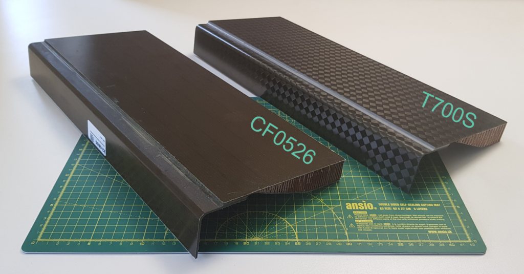
Figure 1. Photographs of the panels.

Figure 2. Technical drawing of L-flange. Drawings are shown from (a) an isometric view, (b) a top view of the panel without the L-bend, (c) a side view of the panel with the L-bend, and (d) an end view. The dimensions are nominal and are in inches.
SOLUTION
The L-flanges were inspected with a dolphicam2 and a TRM-CI-5MHz transducer module (TRM). This TRM has a central frequency of 5 MHz, and it is our highest frequency TRM with an Aqualene delay line. Aqualene is a rubbery material that enables good conformance to rougher and curved surfaces. With a central frequency of 5MHz, the TRM sits in the middle of our range and is a fantastic all-rounder with it being well-suited to both metallic and composite applications.
Standard ultrasonic gel was used as a couplant.
The TRM was moved along the outer radii and held such that the face of the TRM is tangential to the curvature as shown in Figure 3a. The locations of the defects were identified, and then manually-stitched C-scans were acquired along ~1″ wide strips that traversed over the defect locations as depicted in Figure 3b.
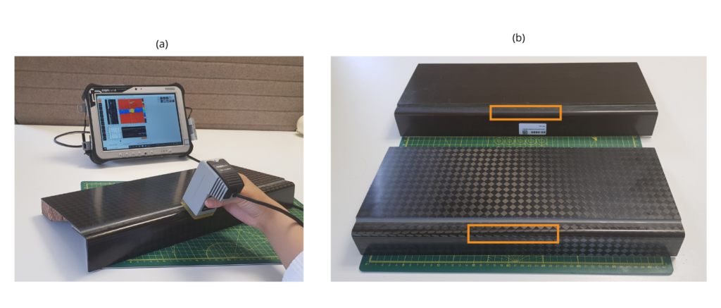
Figure 3. Photographs of (a) the setup on the panel using a dolphicam2 and TRM-CI-5MHz transducer module (TRM), and (b) the panel with an overlay of the scan region.
CHALLENGES
The curvature of the radii makes it more difficult for the TRM to maintain contact with the part. Often specialist solutions are needed. However, we can successfully inspect curved parts including radii using our transducers with our standard delay line made of Aqualene. With the dolphicam2’s live C-scan display, the contact area vs the non-contact area is clearly visible, so users can ensure correct transducer positioning.
FINDINGS
All reflectors were successfully resolved for both L-flanges, see Figures 4 and 5. Even though the full square aperture of the TRM is not in contact with the part, the Aqualene delay line conforms to the curvature, and it is possible to inspect a central strip in contact with the TRM. The TRM can be moved about the curvature, but here the TRM is moved along the edge and the stitched scan is acquired.
In the strip that is in contact with the part, it is possible to see the conformance of the delay line to the radii in the front wall echo and the curved back wall echo in the vertical B-scan. Along the strip, there are two reflectors that can be seen in the scans. Using the line measurement tool, the sizes of the reflectors are measured to be ~0.25″ and ~0.51″ for the CF0526 panel, and ~0.24″ and ~0.50″ for the T700S panel. For comparison, the nominal sizes for the reflectors are 0.25″ and 0.5″ for both panels, so the measured dimensions agree well with the nominal ones. Although these are axial measurements only, corresponding radial dimensions could be acquired by physically rocking the transducer around the radius and taking a line measurement on the C-scan image.
It is clear to see in the red regions above and below the central strip that the full aperture is not in contact with the part. In the B-scans, this can be viewed as a relatively flat front wall corresponding to the depth of the delay line (which is set to be at about 0″) with no features or a back wall behind this since the part is not in contact with the part. In the C-scan, it shows up as a relatively constant shade of red region corresponding to the front wall depth. The appearance of the off-sample region can be used as a visual guide, but if desired, it is also possible to electronically reduce the aperture to eliminate this area.
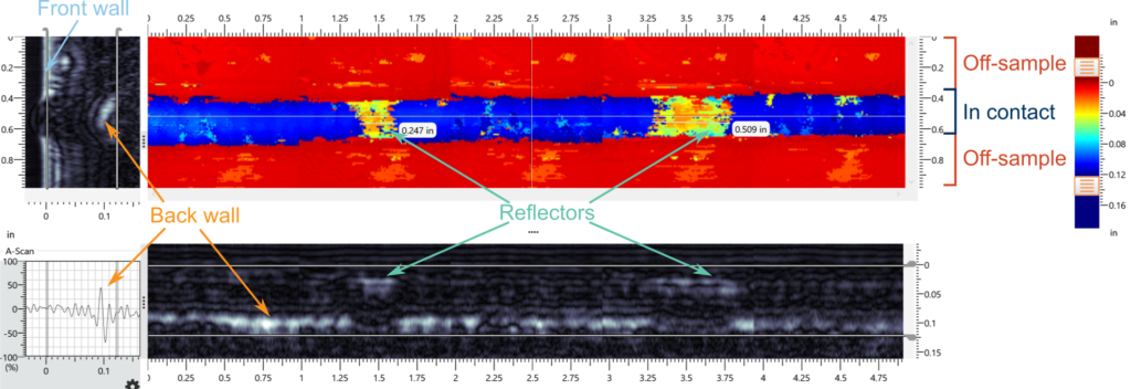
Figure 4. Scan of the reflectors on the CF0526 L-flange. The images in the grayscale color palette are the B-scans (the upper left one is the vertical B-scan, and the bottom is the horizontal B-scan) while the image in the rainbow color palette is the thickness (ToF) C-scan.
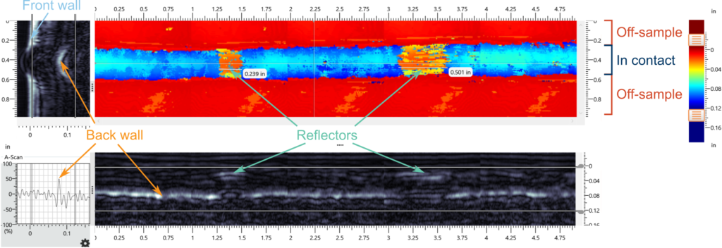
Figure 5. Scan of the reflectors on the T700S L-flange. The images in the grayscale color palette are the B-scans (the upper left one is the vertical B-scan, and the bottom is the horizontal B-scan) while the image in the rainbow color palette is the thickness (TOF) C-scan.
CONCLUSION
The dolphicam2 with a TRM-CI-5MHz transducer module (TRM) was able to successfully inspect the 0.3125″ corner radii. All the manufactured flaws were clearly resolved and sized. The use of Aqualene, a slightly rubbery material, for the delay line enabled the TRM to conform to the curvature of the part.
AEROSPACE
Dolphicam2 is certified by two of the world’s leading aircraft manufacturers – Boeing has authorised specific NDT procedures for their 787 aeroplanes, and Airbus has accepted the dolphicam2 for all composite inspections on its assets.
Read more
Dolphicam2+
Portable, rugged NDT system featuring the largest screen (14″) on the market, offering intuitive ultrasonic flaw detection with advanced imaging capabilities and rapid setup.
MAUT Core Units
TRM 5 MHz
The 5MHz transducer module (TRM) sits at the middle of our range and is a fantastic all-rounder.
MAUT Transducers (TRMs)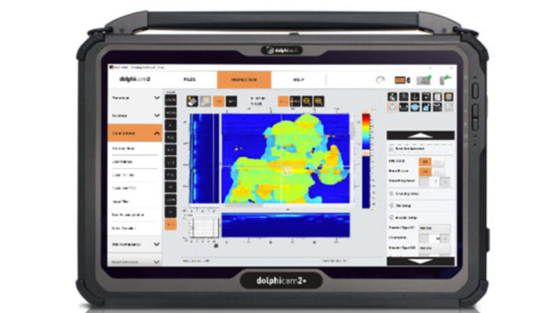
Dolphicam2+
Portable, rugged NDT system featuring the largest screen (14″) on the market, offering intuitive ultrasonic flaw detection with advanced imaging capabilities and rapid setup.
MAUT Core Units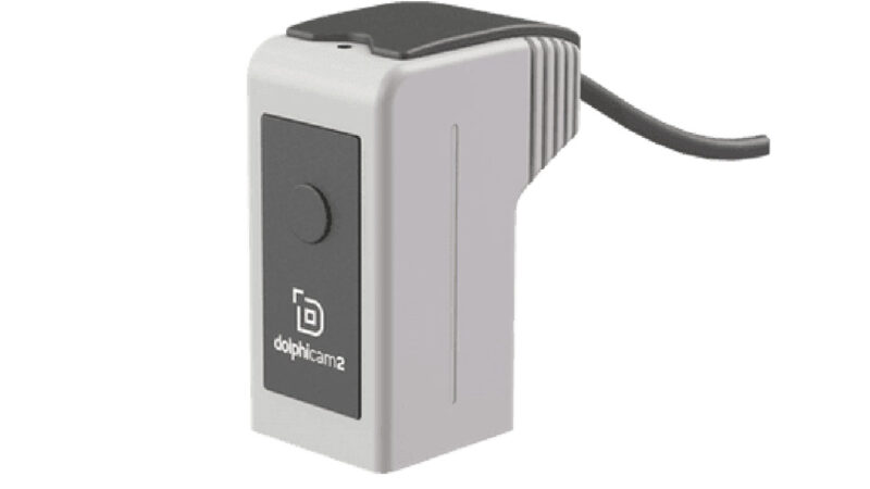
TRM 5 MHz
The 5MHz transducer module (TRM) sits at the middle of our range and is a fantastic all-rounder.
MAUT Transducers (TRMs)REQUEST A QUOTE OR SUBMIT AN ENQUIRY
Need help with product information?
Get in touch with our experts for information or a quotation.