STUDY OVERVIEW
Glass Fibre Reinforced Polymer (GFRP) is used as the predominant material for wind turbine blade construction. As such, it is important the GFRP can be inspected non-destructively, both in terms of the monolithic GFRP laminates and the adhesive bonding between them. This is true both during fabrication and in service, where damage due to fatigue, impact, overload or environmental degradation may develop. Common material imperfections in production include resin starvation, porosity, voids within the adhesive bonding and wrinkling. Common damage modes in service include delaminations, fibre fracture, cracking, lightning strikes, and erosion.
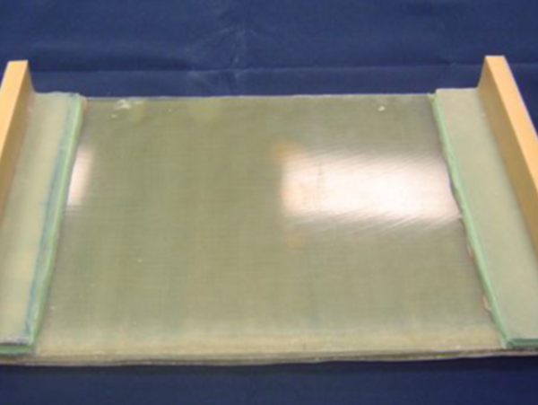
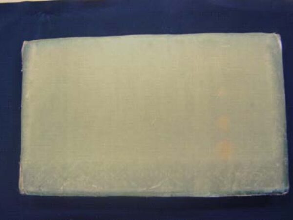
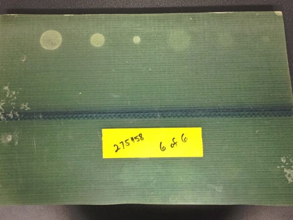
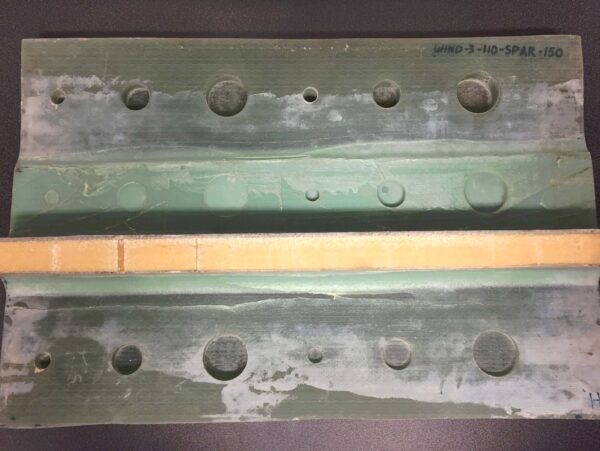
Photographs of Panel 1, which is 30mm thick GFRP representative of wind turbine blade shell material. The additional bonded strips visible on the back face of the sample (left hand side) are representative of shear web bonding.
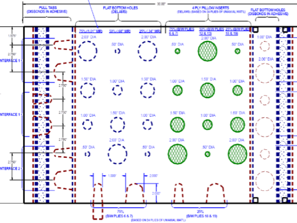
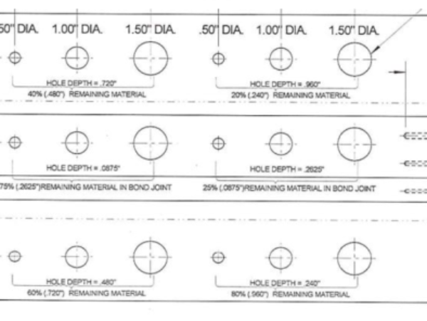
Sandia National Laboratories kindly provided dolphitech with access to two GFRP test panels from a large experimental project into the NDT of wind blade materials. Primary thicknesses of the two panels were 30mm and 32mm, with both panels having additional adhesive layers below these laminates to simulate skin to spar bonding. Both panels contained a range of representative defects in both the laminate and adhesive bonding layers. This included pull tabs, pillow inserts and flat-bottomed holes.
SOLUTION
A TRM-EA-1.5MHz was used to inspect the GFRP panels, with this low frequency providing confidence in the ability to penetrate through the thickness of all GFRP panels and into the adhesive layer beyond. This TRM model has no delay line, as opposed to our replaceable delay lines or contoured delay lines which could be mounted as needed. In this instance it was used without a delay line since the wear resistant front face can be used in direct contact with the test specimen. This option provides the greatest sound transmission into the part, providing maximum penetration. Data was collected from both panels using a manual stitching technique, where the TRM is moved sequentially over the surface of the panel in a grid pattern, and data acquired at each location.
CHALLENGES
GFRP piping is known to be challenging for ultrasonic testing, as the different material phases present a challenge which causes sound to scatter, be absorbed and/or deviate. This problem, common to all composites, is generally worse in glass fiber compared to carbon due to its higher density, larger fiber diameters and typically higher porosity contents. Low frequency probes are therefore required to adequately penetrate through the material; however this reduces the sensitivity of the inspection.
FINDINGS
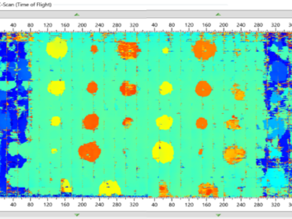
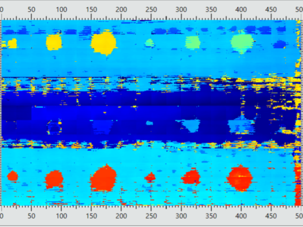
The embedded defects in both panels were successfully detected using the dolphicam2 with a TRM-EA-1.5MHz. The flat-bottomed holes, pull tabs and pillow inserts were readily resolved using the Time of Flight (ToF) C-scans. The color-coding of this C-scan map enabled their through-thickness locations to be determined. The additional adhesive layer below the laminate was also visible (dark blue) showing successful penetration to depths greater than 32mm. Flat-bottomed holes within this adhesive layer, representative of adhesive disbonds, were also visible.
CONCLUSION
A TRM-EA-1.5MHz is well-suited for the inspection of thick wind blade GFRP. In this study, wind turbine-specific panels were successfully inspected, with embedded defects easily resolved and color-coded for straightforward analysis.
REQUEST A QUOTE OR SUBMIT AN ENQUIRY
Need help with product information?
Get in touch with our experts for information or a quotation.

