Exploring dolphitech MAUT technology
Ultrasound NDT (Non Destructive Testing) has existed for over a century and is widely used in several market segments for many applications and for many types of material. In the beginning, one simply used a single element transducer to interpret a single pulse-echo signal known as the A-scan. This technology or method is today referred to as “conventional UT” or Ultrasonic Testing.
Later, 1-D Array transducers were introduced, and is today referred to as “PAUT” – Phased Array Ultrasonic Testing. The industry refers to it as “phased array” since you can steer or phase the ultrasound beams by delaying the transmitting of each transducer element.
About a decade ago, dolphitech, introduced the Matrix Array Ultrasonic Testing (MAUT) which is a row-column (2D Array) transducer principle. After a decade in the industry, MAUT has grown to be an accepted alternative ultrasound technology. One of the latest standards for MAUT is ASTM E3370-22 “Standard Practice for Matrix Array Ultrasonic Testing of Composites, Sandwich Core Constructions, and Metals”.
MAUT versus UT and PAUT
To understand Matrix Array Ultrasonic Testing (MAUT), it is helpful to explore the two other methods of technology mentioned, UT and PAUT. Let us start with the basics of an ultrasound transducer.
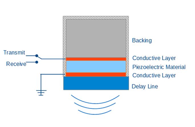
Figure 1 – Basic Components in Ultrasound Transducer
Figure 1 shows the components in a single element ultrasound transducer. The key component in an ultrasound transducer is the piezoelectric material. Above and below the piezoelectric material, you have two conductive layers. The top layer is connected to transmit and receive electronics controlled by a switch, and the bottom conductive layer is grounded.
Sending a high-voltage pulse (for example 100 Volt square wave) into the top transmit conductive layer creates a voltage potential to the opposite grounded layer. This again causes the piezoelectric material to vibrate, and an ultrasound wave is created. The wave will travel through the delay-line and into the material that is inspected. Hence, the job of the delay-line is to transport the ultrasound from transducer into the material and again from material back into the transducer after the pulse-echo.
The role of the backing is to absorb and dampen the wave going “backwards” to avoid disturbing echoes in your measuring data.
When the sound is reflected from the material, back into the transducer, the piezoelectric material will start to vibrate again, creating a small electrical charge into the receiver electronics (the switch will have flipped to receive electronics between the pulse signal and the reflection echo). This small electric charge is then translated into what we call the A-scan.
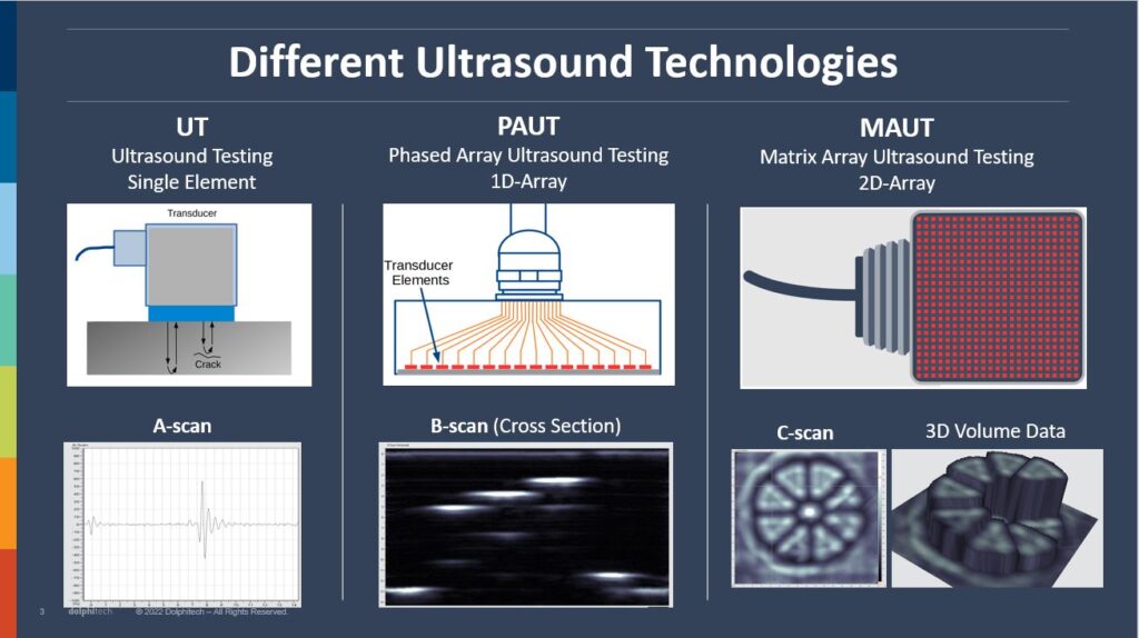 Figure 2 – Different Ultrasound Technologies
Figure 2 compares the three different technologies, UT, PAUT, and MAUT. First conventional UT (Ultrasonic Testing), which is a single element transducer that sends out an ultrasound wave that travels into your material. If there is no flaw in the material, you will see a penetration echo early in your A-scan, and an echo from the back wall of your material later in the A-scan. If the wave hits a crack or other flaw, the reflection echo will appear earlier in the A-scan. The timing and amplitude of this pulse in the A-scan is what the operator uses to interpret the nature of the flaw. This is time consuming and requires a lot of experience to operate and evaluate results.
A PAUT transducer, which is a 1-D Array transducer, has several transducer elements aligned next to each other. This results in many A-scans parallel to each other. If you translate the A-scan values to color values, for example using a gray-scale color palette, you have light colors for high A-scan values and dark colors for low values. This view is called a B-scan and is a “slice” through your material. So now you have a 2D image showing width and depth of your inspection data. This is significantly easier to interpret compared to the conventional UT.
Finally, for the MAUT (Matrix Array Ultrasonic Testing) transducer, you have transducer elements in two directions, both in X and Y direction. Consequently, the elements now cover an area rather than just a point (UT) or a slice (PAUT). This makes it a Matrix Array. Each of these elements are used for pulse-echo and each element therefore results in an A-scan. This adds one more dimension compared to PAUT and makes the result even easier to interpret. You now have volume data or 3D data, and you can view your results in planar view (known as a C-scan) or in a 3D presentation, in addition to B-scans and A-scan. This gives you a lot more flexibility in representing the NDT results and makes the results from MAUT far easier to interpret than UT and PAUT. This reduces the need for competence of the operator and speeds up inspection.
dolphicam2 MAUT Transducer
The MAUT dolphicam2 transducer is formed by 128 transmitting electrodes crossing 128 receiver electrodes as you can see in figures 3 and 4. In between the layer of transmitting and receiving electrodes, is the piezoelectrical material that creates the ultrasound. The cross sections between each transmit electrode and receive electrode create the transducer element that results in an A-scan. Hence 16384 elements and A-scans. The majority of dolphicam2 transducers are 128 x 128 elements (2.5MHz, 3.5MHz, 5.0MHz, 8.0MHz, 10.0MHz), but they also offer a 64 x 64 element transducer (1.5MHz) and a 32 x 32 element transducer (0.7MHz)
![]()
Figure 3 – dolphicam2 transducer – crossing electrodes with piezoelectrical material in middle
![]()
Figure 4 – dolphicam2 transducer – Matrix Array formed by crossing electrodes in row-column-addressing.
MAUT Imaging
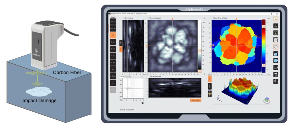
Figure 5 – dolphicam2 views of Carbon Fiber Impact Damage
A-scan, B-scan Vertical, B-scan Horizontal, C-scan Amplitude, C-scan Time-Of-Flight, 3D views.
Dolphitech, has developed an MAUT platform called dolphicam2 (succeeding the first generation of dolphicam1). Figure 5 shows all the views that dolphicam2 provides with the volume data from MAUT. The example data is from an impacted sample of CFRP (Carbon Fiber Reinforced Polymer). These images show a result of a Matrix Array Transducer that has 128 x 128 elements. Hence there are 16384 A-scans. Looking at the views in figure 5, by moving the crosshair in the C-scans shows the corresponding A-scan in that point. The crosshair also decides where you want to slice your data and show the B-scan vertical and B-scan horizontal. The C-scan Amplitude (grayscale) is based on the max peak amplitudes in your data, giving you an incredibly detailed view of the pulse-echo reflected in your material. The C-scan Time-Of-Flight (color), provides the user with a very precise view of the depth and thickness of the reflected pulse echo. Lastly, there is a 3D view which can be zoomed and rotated to give a very intuitive representation of the data.
NDT Applications using MAUT
The dolphicam2 MAUT platform can be used for a wide range of materials and NDT applications. One of Dolphitech’s main markets is the composite industry (carbon fiber and glass fiber), inspecting flaws such as impact damage, delamination, porosity, in aerospace, automotive and wind energy. The technology is also used on metallic applications like corrosion in pipes and tanks, crack detection, adhesive joints, etc.
Below are two inspection results. Figure 6 shows the impact damage on a Boeing 787 Aircraft. The fuselage was accidentally impacted by a ladder. The impact resulted in a disbond between the fuselage and the stringer from the inside frame. Figure 7 is also an example from aviation and shows a corrosion from a 3 mm thick aluminum alloy. The C-scan images show the corrosion results.
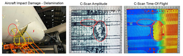
Figure 6 – Impacted Composite Aircraft Boeing 787 (Dreamliner)
C-scan Images show that fuselage is disbanded from stringer frame
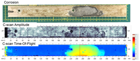
Figure 7 – Corrosion on Aluminum Alloy from Aircraft
C-scan Images show corrosion with detailed depth information.
EXPERIENCE THE DOLPHITECH DIFFERENCE
See more with our innovative NDT technology
Send in a sample to see how dolphitech can reduce inspection lead times and enhance insights
Contact us